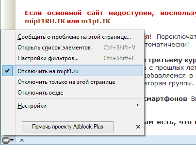
Обнаружен AdBlock
Пожалуйста, отключите блокировку рекламы, хотя бы для сайта mipt1.ru. Вся реклама на сайте ненавязчива и не закрывает контент. Сайт располагается на платном хостинге и не окупается. Если же Вы не хотите видеть рекламу, то воспользуйтесь мобильной версией или получите аккаунт с отсутствием рекламы, пожертвовав сайту сумму от 50 рублей.
Закрыть всплывающее сообщение